|
No pierda la oportunidad de ver las ventajas del COMPROBADOR INTELIGENTE DE BATERÍAS GOLD-IBT.
1.
Section 1
1.1 Chemical Reaction The electrochemical reactions in a lead acid battery when discharged can be easily described with the following formula:
This reaction is reversible and when charged runs in the opposite direction to the above arrow.
1.2 Valve Regulated Technology for Lead-Acid Batteries Main Characteristics
Valve regulated lead-acid batteries are distinguished by the immobilised electrolyte and the vented casing. Each battery cell has a valve through which any resulting hydrogen gas (due to excess pressure in the cell) can be released (typical value: 100 mbar , 114 PSI). The valve closes airtight to external pressures. After release of the hydrogen the valve closes again and prevents 02 entering the cell. The sealed lead-acid batteries are maintenance free for three reasons:
The electrolyte is immobilised either in a gel or by absorption of the electrolyte in a glass fibre separator. This is the AGM (= Absorbed Glass Mat) technology. The electrolyte in the dryfit batteries is immobilised in a gel.
1.3 Plates Dryfit batteries of the series A 200, A 300, A 400, A 500, A 700 and0GiV contain grid plates. These gravity cast lead grids, produced for positive and negative plates, are pasted with a lead oxide paste, cured and then formed. The positive plates for the series A 600 are tubular plates for which the dry raw material (powder) is vibrated into polyester gauntlets. The plates are then cured and formed.
1.4 Separator The separator separates the positive and negative plates mechanically and electrically from one another. It must not only guarantee a high porosity to allow electrolyte acceptance and ion migration, but it must also prevent short circuits.
1.5 Electrolyte Gel System The electrolyte in the dryfit batteries is immobilised in a gel (sulphuric acid: H2S04). The gel is a mixture of sulphuric acid, water and SiO2. The gel system also offers the possibility of varying the components and to include certain additives for the cycle stability.
1.6 Water Loss and Recombination When the battery is fully recharged water decomposition takes place causing water loss. In the valve regulated lead-acid battery the water decomposition is almost fully compensated by the recombination of the oxygen on the negative plates. This oxygen recombination is made possible by the immobilised electrolyte. As the speed of diffusion of oxygen into sulphuric acid is very low, there is hardly any recombination in a conventional lead-acid battery. However, in batteries with the gel electrolyte system channels are formed through with the oxygen (which forms on the positive plate) can migrate to the negative plate without any interference. The dryfit system electrolyte reserve is regulated so that the service life is not influenced by the water loss.
1.7 Casing The dryfit batteries are available with the following casing material:
As special type up to 16 Ah : Acryinitrile-butadienestyrene-copolymer (ABS) (UL94-VO) for 20 - 200 Ah : Polypropylene (PP) (U L 94-V2)
ABS UL 94-VO on request.
For the series A 200, A 300, A 400 and A 500 the nominal capacity is given for discharge at the 20 hour rate. Discharge with constant current for the period of 20 hours corresponds to CN. The final discharge voltage UE with which the discharge is terminated is 1.75 V/cell.
For the series A 600, A 700 and 0GiV the nominal capacity is given for discharge at the 10 hour rate. The final discharge voltage UE for the nominal capacity C10 is 1.8 V/cell.
The nominal capacity of solar batteries is given at the 100 hour rate, C100 (final discharge voltage 1.85 V/cell) and the series A 500 C nominal capacity is given at the 5 hour rate, C5 (final voltage 1.7 V/cell). The capacity of valve regulated lead-acid batteries depends on the temperature and the output current (cf. fig. 2). Discharge within the electrolyte-freezing zone could lead to destruction of the battery. The final discharge voltage and discharge times, as well as the characteristic currents can be taken from the discharge curves in the brochures on the respective series. The discharge curve for the A 500 is given below as an example (cf. fig. 5). With currents lower than I20 or I10 the battery output can exceed the nominal capacity. With currents higher than I20 the battery output is lower than the nominal capacity.
The cell nominal voltage UN is a fixed value. The nominal battery voltage results from the number of cells and the nominal cell voltage (2 V).
4.1 Final Discharge Voltage The final discharge voltage is specified as the value below which the voltage must not fall when discharge occurs at the respective current. If the battery is discharged further, (i.e. the battery voltage is lower than the final discharge voltage), the area of deep discharge is entered. The final discharge voltage is normally given in V/cell and depends on the discharge current.
4.2 Discharge Current The discharge current in multiples n I20 or I10 for a 1X, current can be determined using the following formula: n = 1X . 20 h or
n = 1X. .10 h The following maximum discharge currents are stated in the series brochures for the dryfit batteries :
4.3 Depth of Discharge The capacity taken from the battery is termed as the depth of discharge. For example, if 80% of the nominal capacity is used from the battery then the depth of discharge is also 80%. The maximum permitted depth of discharge depends on the level of the discharge current and the temperature.
4.4 State of Charge An approximate determination of the state of discharge by measuring the open-circuit voltage is possible with a tolerance of about 15% (cf. Open circuit voltage, fig. 4).
4.5 Deep Discharge The battery enters the deep discharge zone when :
All data for deep discharge refers to single batteries. With a series of blocks or cells different behaviour may occur with respect to the depth of discharge. In accordance with DIN 4353 9, Part 5, the deep discharge test is defined as follows : A battery having at least its nominal capacity is bridged with a load resistance. The load resistance is selected so that the discharge current with a cell voltage of 2V/cell lies in the range between 2. IN and the maximum permissible discharge current. The battery is stored at room temperature for 30 days. At the end of the storage period the battery is charged for 48 hours. The following capacity test must show a capacity of over 75%.
During the discharge of lead-acid batteries the acid density decreases giving a low conductivity for deep discharged batteries. This effect is compensated for in dryfit batteries by additives to the electrolyte which increase conductivity. A surplus volume in the plates is formed by increased lead sulphate formation, which represents a mechanical load for the system. dryfit batteries are constructed to withstand the increased load largely without damage. Deep discharge should be avoided. Sulphation of the plates con also occur if the batteries are discharged with discharge currents < 0,2 . I20. The batteries can then only be charged with a suitable charge process e.g. a charge with the IUI-characteristic (cf. fig. 8).
4.6 Discharge Voltage The discharge voltage is the battery voltage during the discharge process. As an example figure 5 shows the discharge curves for various discharge currents for the A 500. The diagram shows the time during which the respective current can be drawn, the battery discharge voltage and the final discharge voltage at the discharge current.
Dryfit batteries can be charged with the most simple recharging methods.
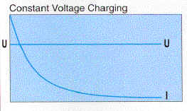
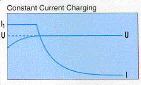
5.1 Charging Characteristic Constant Voltage Charging
IU-characteristic Charging
IUI-characteristic Charging
Fully charged condition
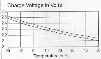
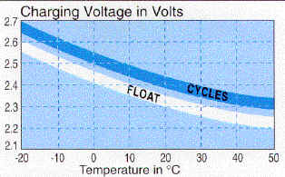
5.2 Charging Voltage The charging voltage is determined by the recommendation given by the manufacturer for each battery type.
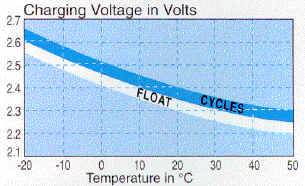
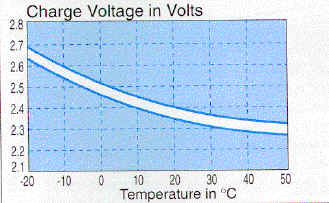
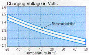
5.3 Temperature Compensation of Charging Voltage Temperature compensation of the charge voltage is necessary when the temperature fluctuates, to avoid increased gassing at higher temperatures. We recommend the following temperature compensation
The individual temperatures within the battery must not vary by more then 30C when installing blocks/cell.
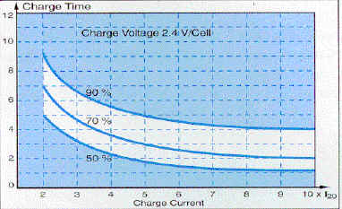
5.4 Recharge Time
5.5 Charge Currents We recommend the following nominal currents for dryfit batteries
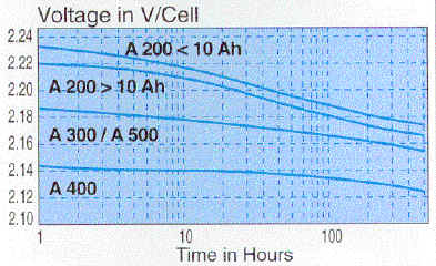
The open-circuit voltage potential can only be measured on stored batteries. This means : the open-circuit voltage potential can only be determined after a storage period of at least 2,4 hours and not immediately after charge or discharge. The open-circuit voltage potential depends on the state of charge and the temperature.
Permissible ripple current causes warming of the battery. During charging the temperature increase is not to exceed 30C.
9.1 Installation and Ventilation When installed in containers, cabinets, etc. the VDE 0570, Parts 2 and 7, must be adhered to, as hydrogen in a volumetric concentration of more than 4% forms an explosive mixture. dryfit battery gassing is extremely low. The required maximum gas volume of 30 ml per 1 Ah and cell in 30 days for the series A 200, A 400, A 500, A 600 and A 700 in the proposed IEC 896, Part 2 (currently a draft) is adhered to.
9.2 dryfit Battery Transport Based on tests the following regulations have been specified for new and used dryfit batteries : Dangerous Goods Regulations for Road Transport
(German GGVS) : "dryfit batteries are not classified as dangerous
goods"
9.3 Storage When dryfit batteries are stored fully charged
9.4 Disposal and Recycling Your old dryfit batteries will be taken back without any problems by the following:
Sonnenschein and the smelters recycle the lead and plastic materials in the batteries. Batteries are taken back under the following conditions:
The service life for dryfit batteries in constant charge operation, is the period of time after which the battery has only 80% of its nominal capacity C20 i.e. C10. This is valid for discharge at I20 up to UE = 1.75 V/cell i.e. I10 up to UE = 1,8 V/cell at room temperature. The service life of the battery is an important factor for the standby parallel operation. The service rife of the battery depends on the temperature and can only be reached if the given charge voltage is adhered to. The diagrams show the service life in relation to the temperature. Other parameters with influence on the service life are :
Apart from the service life, the cycle endurance is also defined. The cycle endurance is applied when the battery is not used in standby parallel operation. Currently, the standard definitions are to be applied according to the following controls:
The number of cycles which a battery can perform, depends on the battery construction and the depth of discharge. The number of cycles a dryfit battery can perform in accordance with the above tests is given in the selection table in section 14.
Dryfit batteries have an extremely low self-discharge. This is a positive characteristic of the gel technology.
The total battery resistance is the accumulation of all internal cell resistances and all connection resistances within the battery. (cf. DIN 40729). To calculate the RIG total resistance of the battery the following formula is valid at room temperature (20-250C) for a in a fully charged condition.
For example, for A512/6.5:
The internal resistance depends on the temperature and the state of charge.
14.1. Dryfit Selection Table
*Series
A600 WE: The series A600 is available for horizontal installation as A600WE
14.2 Brief Type Description with National and International Classifications A200 Series
A300 Series
A 400 Series
A 500 Series
A 500 C Series
A 600 / A 600 WE Series
A 700 Series
|
|||||||||||||||||||||||||||||||||||||||||||||||||||||||||||||||||||||||||||||||||||||||||||||||||||||||||||||||||||||||
|
|